Lab 1
Lab Goals
Learn basic functionalities of the Arduino Uno, the Arduino IDE, and the GitHub repository. In particular, focus on writing a program to control multiple external components connected to the Arduino Uno. At the end of the lab, put together a robot and have it perform a simple autonomous task.
Prelab
- Setup GitHub accounts and create team website
- Review the Arduino Reference
- Review documentation for the Parallax Continuous Rotation Servo
Sub-Teams
To begin, we split into two groups of two. Each group progressed through the lab individually, as described below.
- Brian and Tyler
- Eric and Kenneth
Materials Used
- 1 Arduino Uno
- 1 USB A/B cable
- 1 Parallax continuous rotation servo
- 1 LED (not IR)
- 1 10kΩ Potentiometer
- Several resistors (kΩ range)
- 1 Solderless breadboard
Part 1 — Communicating Between the Uno and the IDE
GOAL: use the Blink sketch to control an internal LED
- Install Arduino IDE → Download Link
- We first tested the example code “Blink”
- This example can be found under: File > Examples > 1.Basics > Blink
- An Arduino program is known as a “sketch”
- In the IDE, click checkmark to compile the code
- In the IDE, click right-pointing arrow to upload (program) the Uno
- If the LED does not blink, check under Tools > Serial Port list to make sure that the Uno is connected to the correct COM port
All Arduino sketches require two functions:
void setup() {}- Called at the start of the entire program
- Used to initialize variables and setup I/O pins
- Only executes once
void loop() {}- Contains the main body of your program
- Loops forever
Our example sketch code:
      void setup(){
          // initialize digital pin LED_BUILTIN as an output.
          pinMode(LED_BUILTIN, OUTPUT);
      }
- Instructs the Uno that the built-in LED should act as an output
- This allows us to write voltage values to turn the LED on and off
    // the loop function runs over and over again forever
    void loop() {
      digitalWrite(LED_BUILTIN, HIGH);   // turn the LED on (HIGH is the voltage level)
      delay(1000);                       // wait for a second
      digitalWrite(LED_BUILTIN, LOW);    // turn the LED off by making the voltage LOW
      delay(1000);                       // wait for a second
    }
- HIGH and LOW are global variables defined by Arduino, which correspond to logical high (on) and logical low (off)
- Since the LED_BUILTIN pin was set as an output, we can write these logical values to it
- The program delays for 1 second in between each high / low write (time units are in ms → 1000 ms = 1 second)
Part 2 — Modify the Blink Sketch
GOAL: modify the Blink sketch to control an external LED
- The code is identical to that of the Blink example, except for the pin number that the I/O functions use
- Replace “LED_BUILTIN” with the pin number that the LED is connected to
- Use the LED with every digital pin to test that they all work
- As a safety measure, connect the LED in series with a 300 Ohm resistor.
- In the event of a complete short out, this limits the output current to I = V/R = (3.3V/300Ω) = 0.011 A.
- Below we show the LED blinking while connected to digital pin 0
      void setup() {
        pinMode(0, OUTPUT);
      }

      void loop() {
        digitalWrite(0, HIGH);   // turn the LED on (HIGH is the voltage level)
        delay(1000);                 // wait for a second
        digitalWrite(0, LOW);    // turn the LED off by making the voltage LOW
        delay(1000);                  // wait for a second
      }
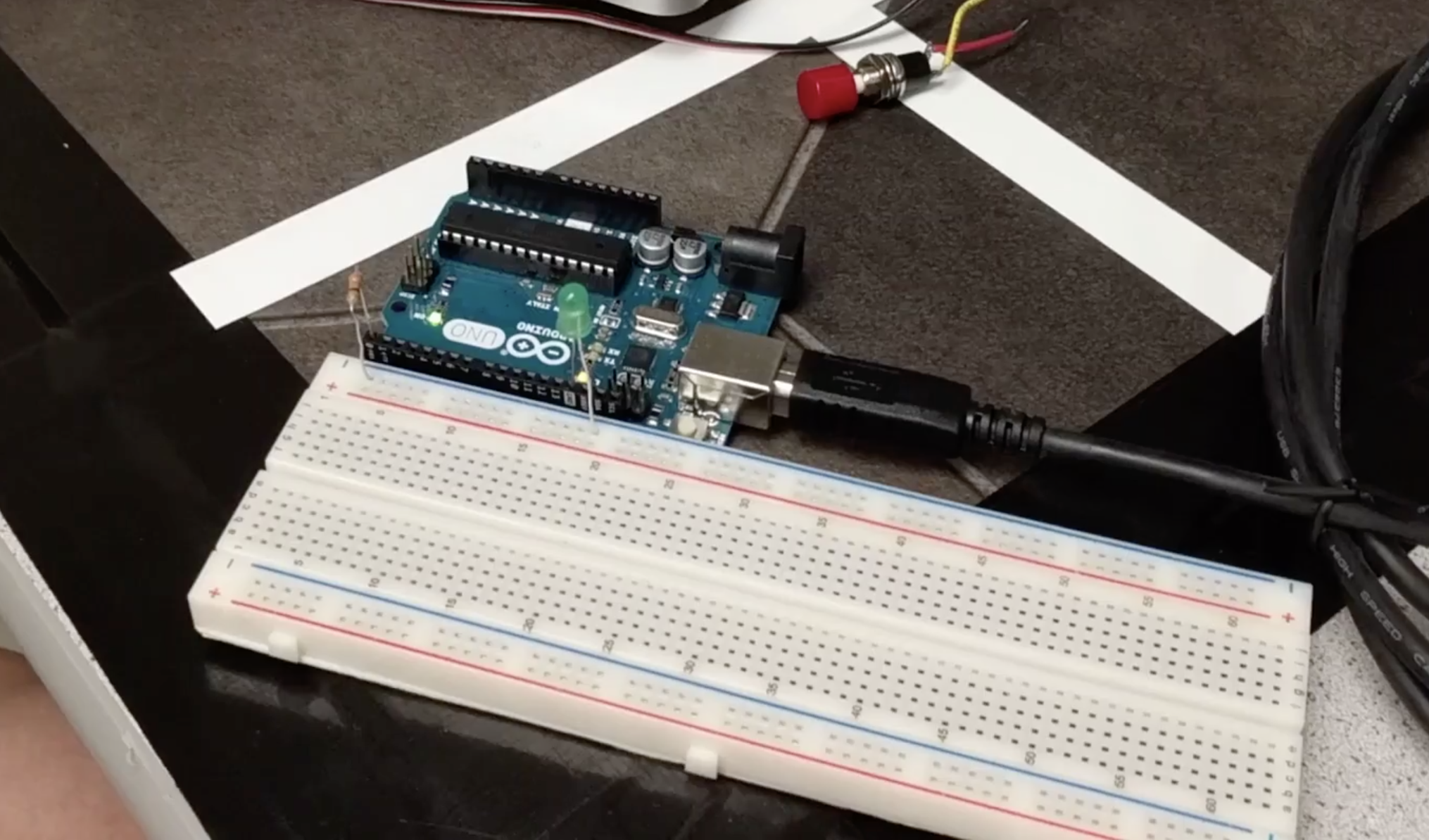
Green LED connected to digital pin 0
Part 3 — The Serial Monitor and the Analog Pins
GOAL: read an analog value and verify it is correct via serial monitor
- Connect a potentiometer in parallel with a resistor
- This resulting output is connected in series with a 300 Ohm resistor to one of the Uno's analog pins
- The voltage values read by the analog pin are printed over the USB cable and displayed in the IDE’s serial monitor
      int readValue = 0;
      int pinName = A0;
- Two variables are declared:
- readValue = the value that is output by the ADC
- pinName = the analog pin number that the potentiometer is connected to
      void setup() {
        Serial.begin(9600);  }
- In setup(), Serial.begin(9600) initializes the serial connection between the Arduino and the computer it is connected to
- The baud rate is specified to be 9600
- Any COM port or serial monitor on the PC side must use the same baud rate in order to correctly transfer data
      void loop() {
        readValue = analogRead(pinName);
        Serial.println(readValue);
        delay(500);
      }
- In loop(), analogRead returns the analog value from the potentiometer
- This is sent to Serial.println, which sends it across the USB cable and to the PC’s serial monitor
- A delay of 500 is used to wait for 0.5 seconds before reading from the analog pin again
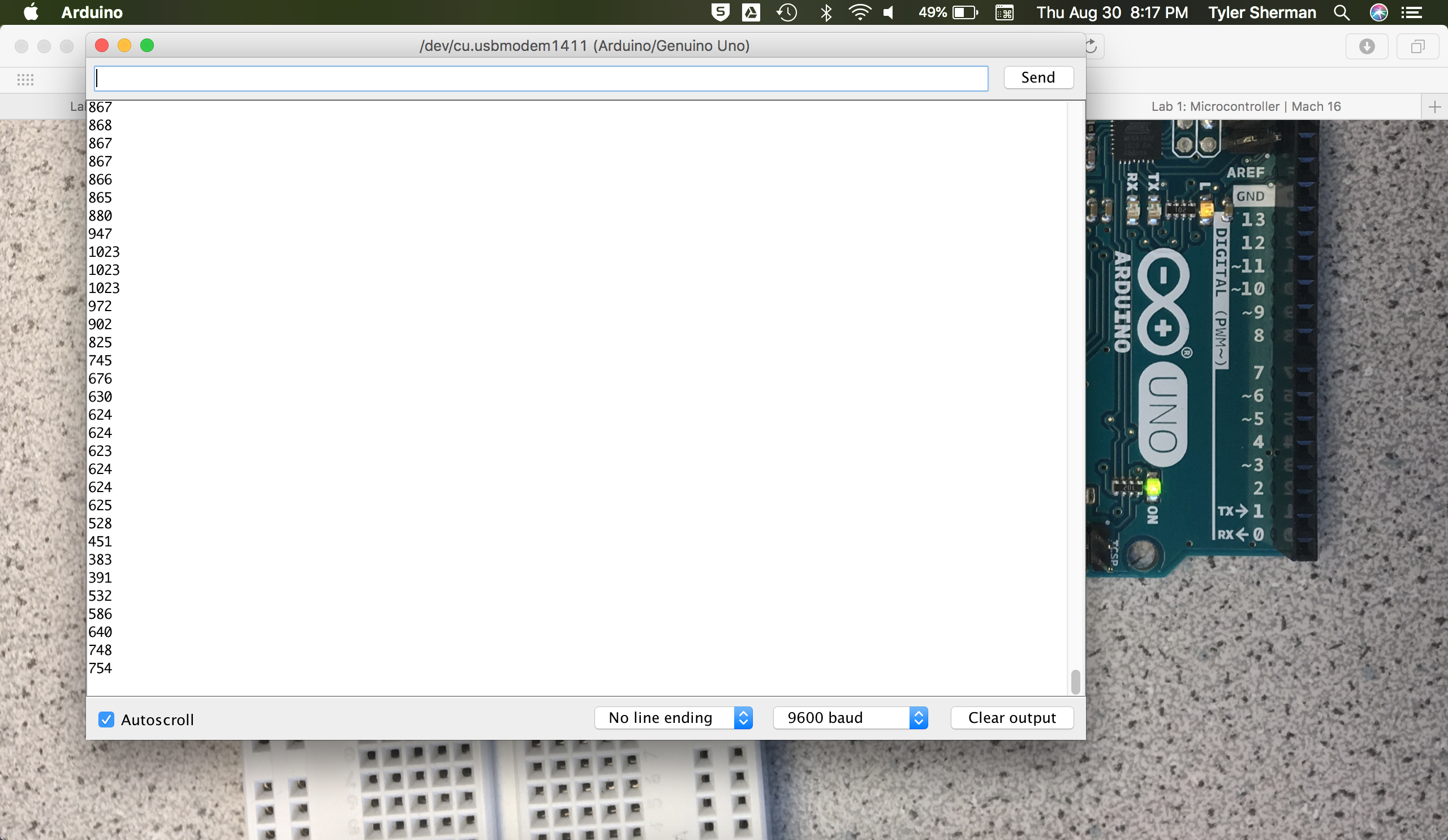
Analog values printed to the serial monitor
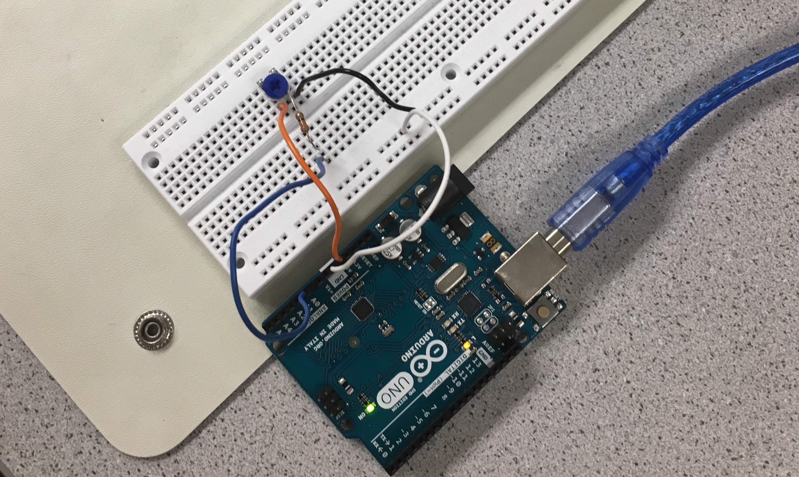
The circuit
Part 4 — Analog Output
GOAL: use a potentiometer to control the speed of a servo
- The Arduino can only output digital signals.
- To simulate an analog output, use a pin with pulse-width modulation (PWM)
- For more information on PWM, look here
- Arduino pins with PWM capability are denoted with a tilde (~) symbol
- To demonstrate this PWM capability, use a potentiometer to vary the brightness of an LED
- The potentiometer provides an analog input to the Arduino
- Function = analogRead()
- Range = (0, 1023)
- A PWM-capable digital output pin controls the LED brightness
- analogWrite()
- Range = (0, 255)
- To handle the range mismatch between analogRead() and analogWrite(), we divided the read values by four (seen in last line).
      int analogInput = A0;
      int digitalPin = 11;
      int voltageValue = 0;
      int delayTime = 500; //half a second

      void setup() {
        Serial.begin(9600);
        pinMode(digitalPin, OUTPUT);
      }

      void loop() {
        voltageValue = analogRead(analogInput);
        Serial.println(voltageValue); //Prints to serial monitor, used for debugging purposes
        delay(delayTime);
        analogWrite(digitalPin, voltageValue/4);
      }
Demo:
Part 5 — Parallax Servos
GOAL: use a potentiometer to control the brightness of an LED
- We connect Parallax continuous rotation servos to the Arduino and set it to run at varying speeds.
- In order to use servos, the Servo library needs to be included in the sketch. This is done with a #include statement at the top.
- A Servo object needs to be declared for each servo that is used. In the example below, “myservo” is the name of the servo that is connected to the Arduino.
- In setup(), myservo.attach(3) connects the servo to pin digital pin number 3. This a PWM capable pin, since servos need a PWM signal to operate.
- In loop(), the last statement, myservo.write(val), writes an integer value ranging from 0 to 180 to set the servo speed. This correlates with the PWM duty cycle that is outputted from the pin. A value of 0 rotates full speed in one direction, and 180 is full speed in the other direction. A value of 90 means the servo will not turn in either direction.
- The two statements above myservo.write() read analog voltage from the pin the potentiometer is connected to and set the servo to a speed corresponding to that voltage value. The map(readValue, 0, 670, 0, 180) function takes in the readValue input, which ranges from 0 to 670, and scales it to an integer value between 0 and 180, which is returned. This allows the potentiometer to control the servo movement.
        #include
        int val = 90;
        int readValue = 0;
        int pinName = A0;
        Servo myservo;

        void setup() {
          myservo.attach(3);
        }

        void loop() {
          readValue = analogRead(pinName);
          val = map(readValue, 0, 670, 0, 180);
          myservo.write(val);
        }
Demo:
Part 6 — Assembling and Running Our Robot
GOAL: assemble the robot and make it perform a short autonomous task
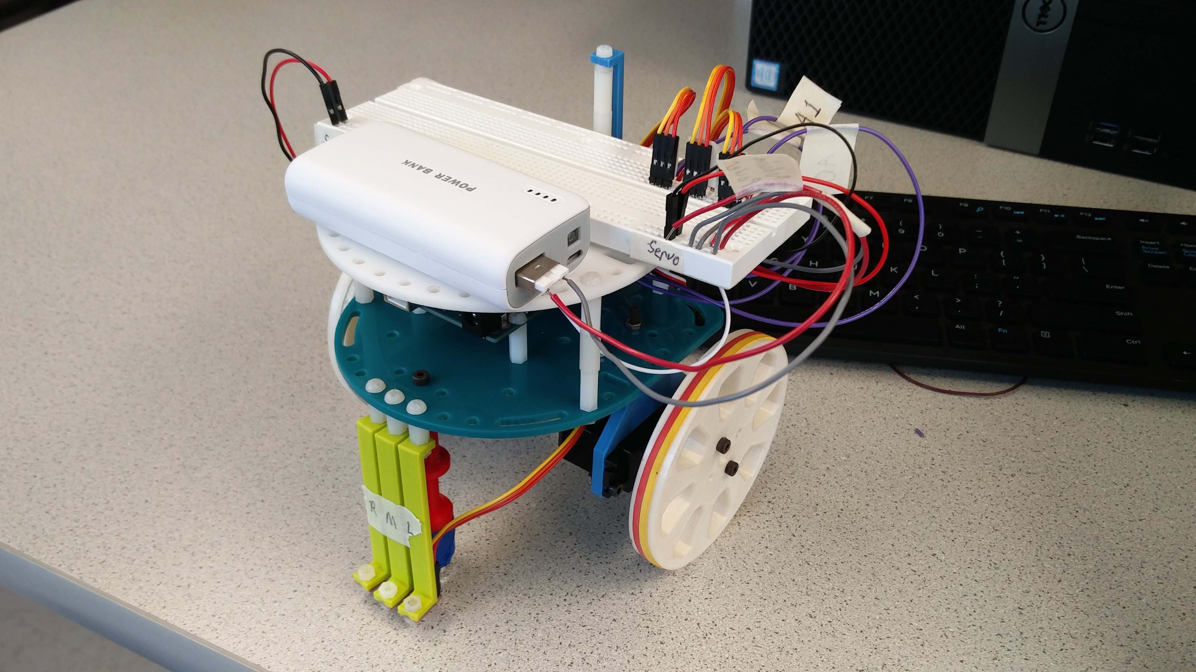
- This week we also assembled our robot and implemented basic autonomous movement
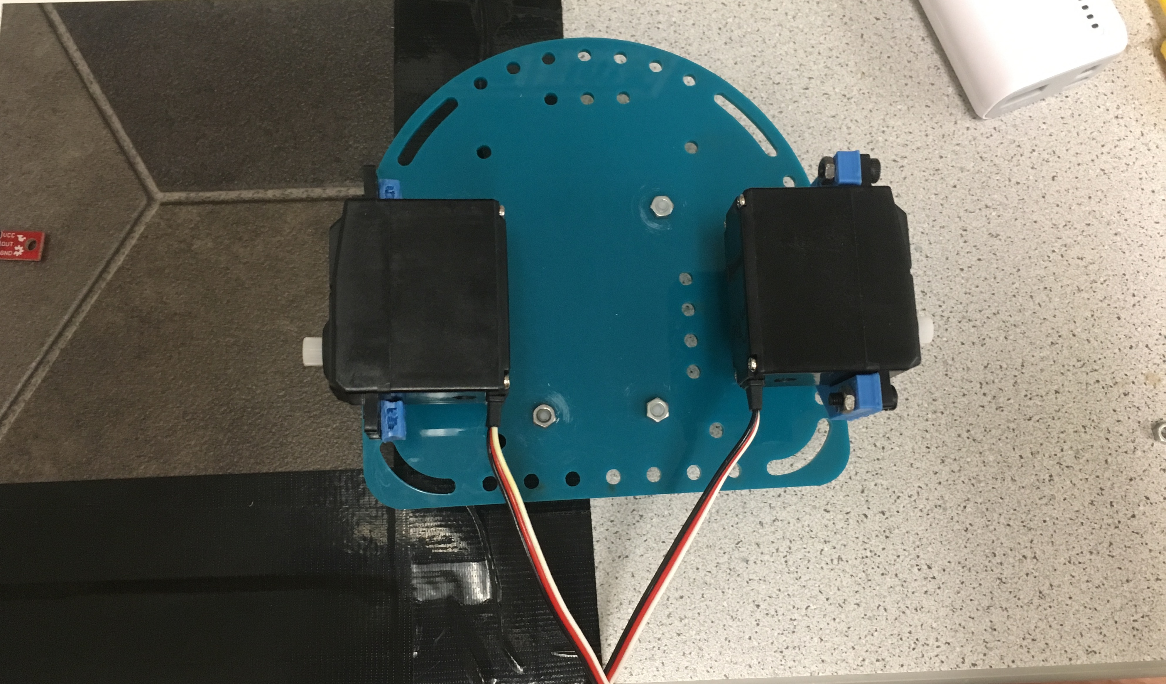
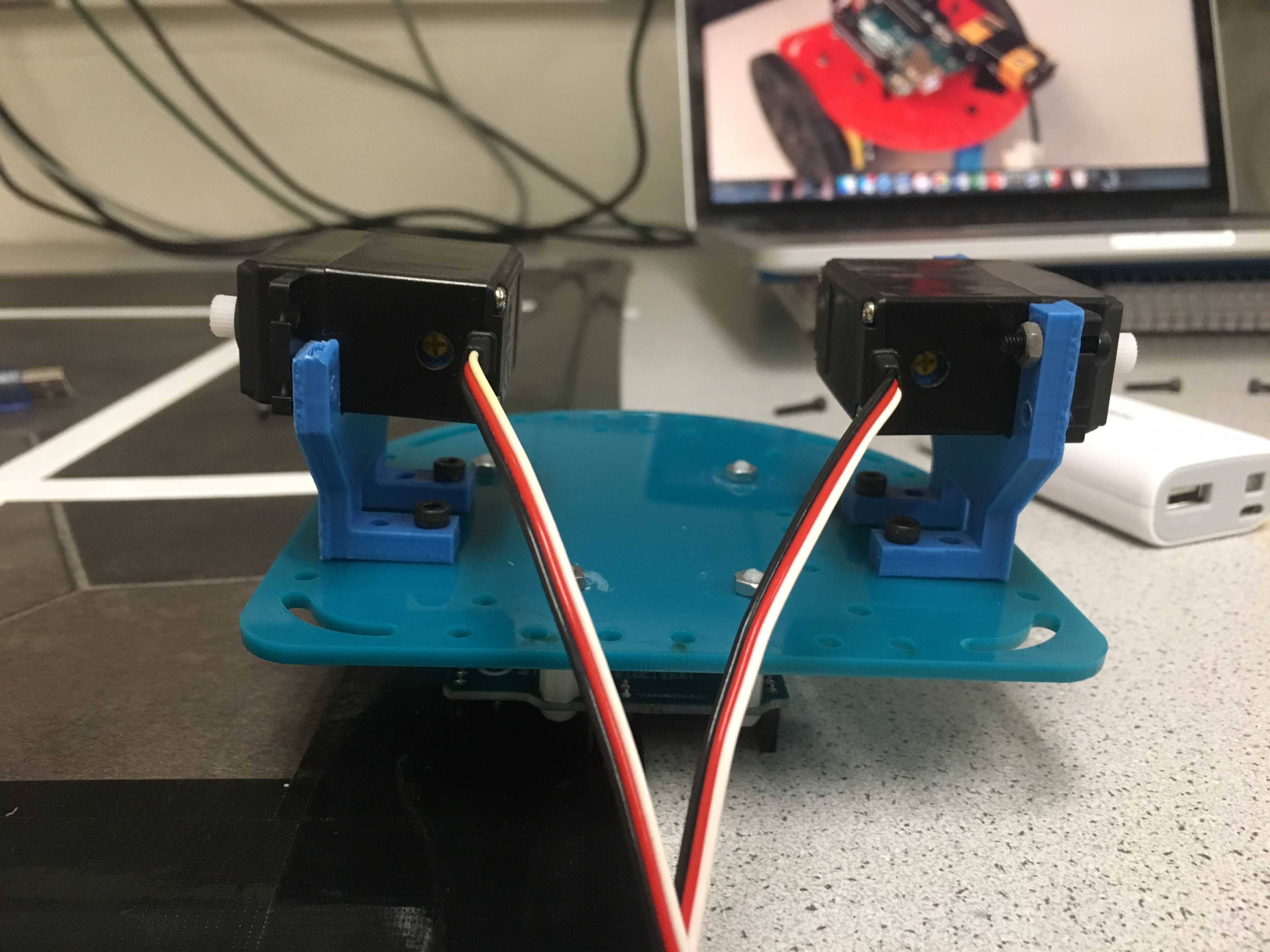
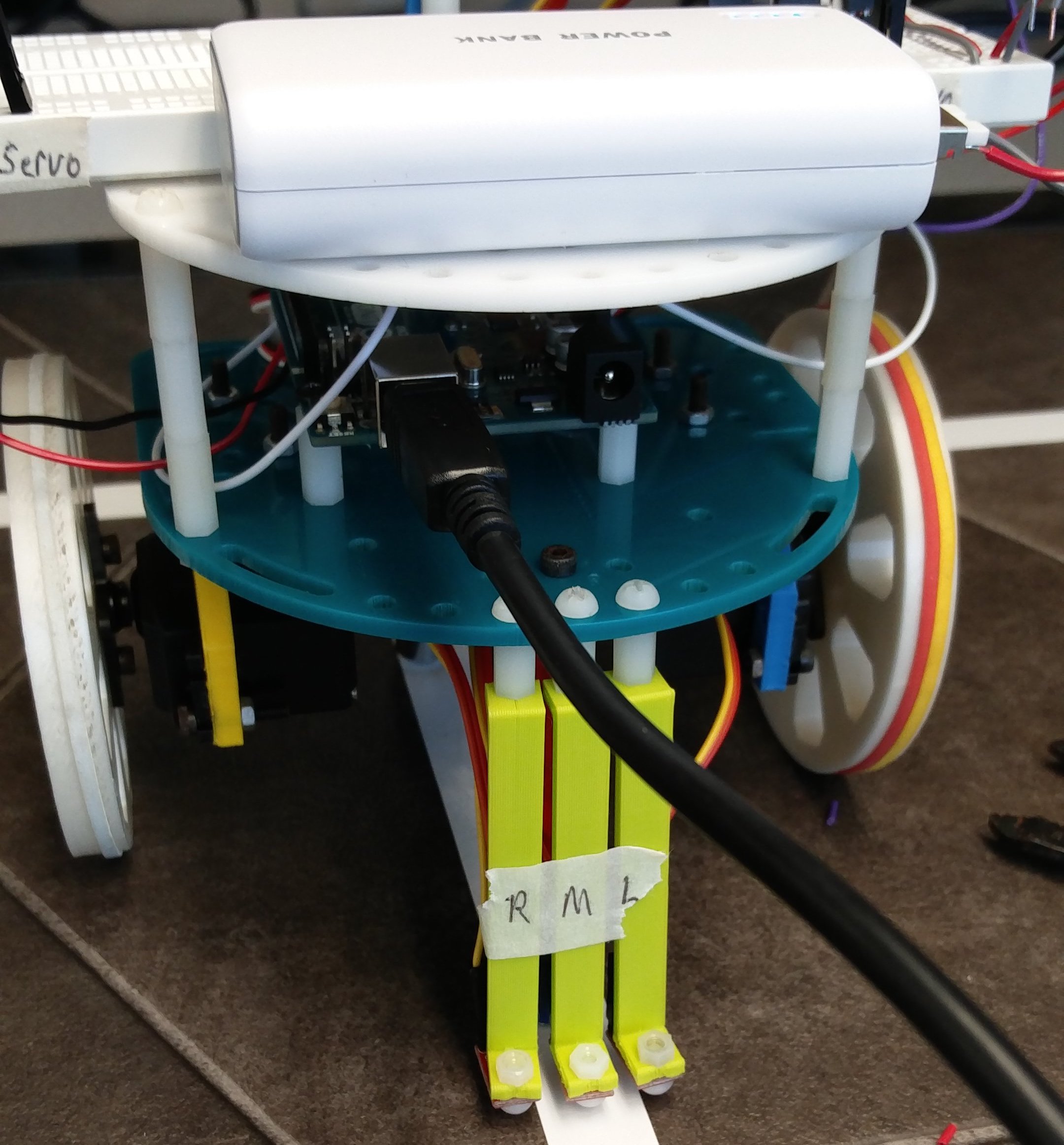
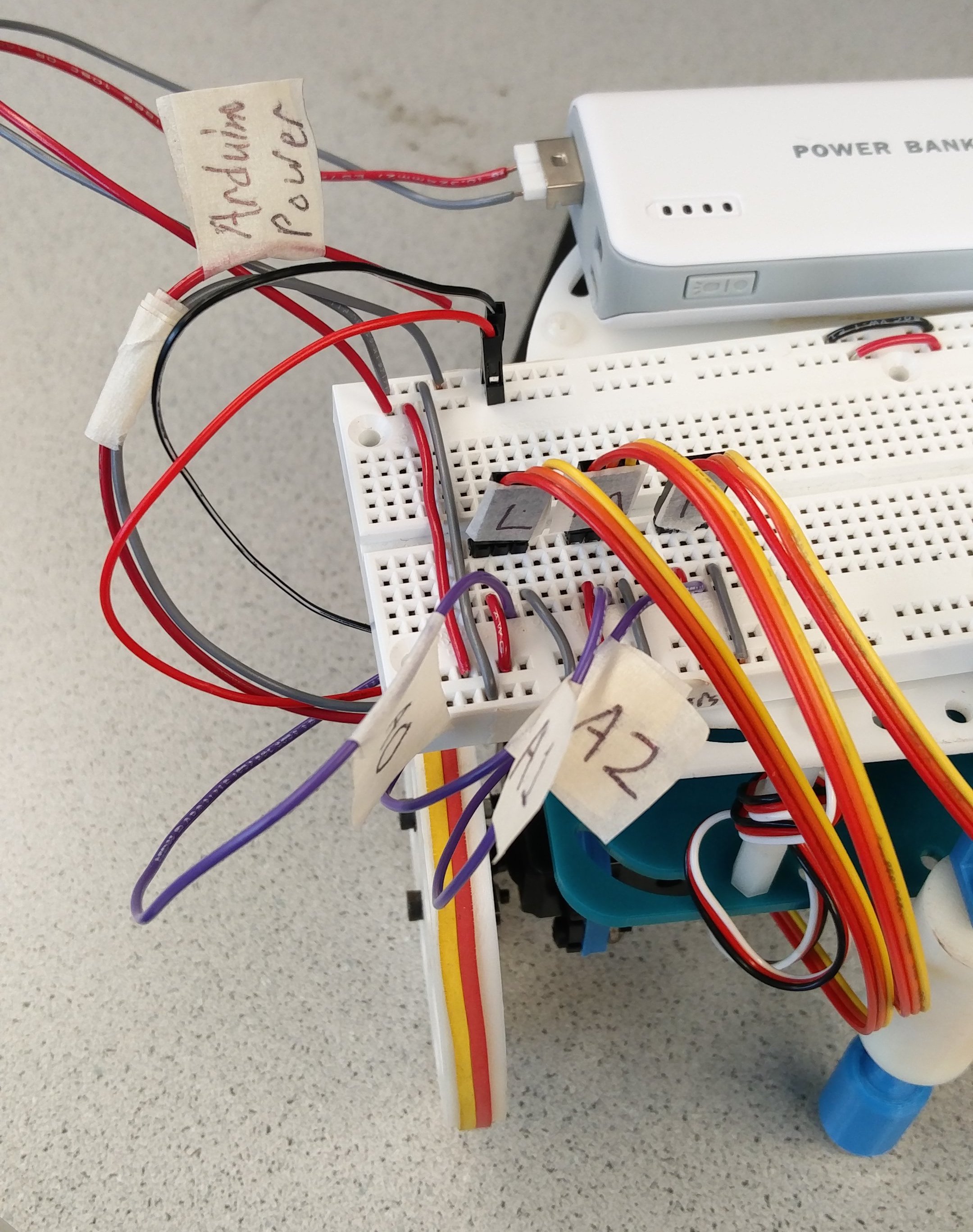
- We built our robot using the 3D-printed and laser-etched parts sitting in the lab room, including:
- 1 robot base (the large aqua platform in the image)
- 1 Arduino Uno
- 1 rechargeable battery
- 1 solderless breadboard
- 2 servo mounts
- 2 Parallax continuous rotation servos
- 2 ball bearings with connectors
- 2 wheels
- 3 rubber bands
- 3 Pololu QTR-1A Reflectance Sensors
- Various wires, screws, nuts, and spacers
- The construction of the robot was tedious and time-consuming
- We modeled our prototype off of last year’s designs (found on their websites)
- See the images below for a detailed overview of the design
For our code, we wrote a header file with the following movement commands:
        // Stops the robot
        void stopMotors(Servo servo_L, Servo servo_R);

        // Drives the robot forward
        void moveForward(Servo servo_L, Servo servo_R);

        // Drives the robot backward
        void moveBackward(Servo servo_L, Servo servo_R);

        // Turns the robot right slightly, based on [amount]
        void adjustRight(Servo servo_L, Servo servo_R, int amount);

        // Turns the robot left slightly, based on [amount]
        void adjustLeft(Servo servo_L, Servo servo_R, int amount);

        // Turns the robot 90 degrees right, in place
        void turnRight(Servo servo_L, Servo servo_R);

        // Turns the robot 90 degrees left, in place
        void turnLeft(Servo servo_L, Servo servo_R);
By running these commands sequentially with delays, we can program our robot to move around in arbitrary patterns. We used these functions to move our robot around a square in the video.